This is starting to get really interesting. Advancing a techno protocol is all about the details. Ultimately this will be a powrr plant able to operate a starship. It really is that important and deserves ongoing serious funding.
New hardware is on hte way which will likely continue the improvement. As usual biggert is better at this stage.
all good
|
|
ICCD Video Reveals Shocks
|
|
A full sequence of images of the current sheath of LPPFusion’s FF-2B experimental device shows that a shock wave is the most likely proximate cause of the disruption of filaments that has limited fusion energy yield. Our rapidly-advancing effort to provide new switches for FF-2B provides a path to eliminating the oscillations that cause these shock waves.
The first stage of operation of our FF-2B fusion experimental device produces a sheath of electric current running through a plasma along a ceramic insulator between our beryllium anode and the cathode that surrounds it. Back in November, 2019, the first images that our ICCD camera provided of the current sheath showed clearly that tight filaments of current were being created inside our FF-2B device. That was good, because the filaments are the first step in compressing the plasma and the more the plasma is compressed, the more fusion yield we get.
However, the images also showed, as we reported in January that the orderly filaments were getting disrupted at the leading edge of the current sheath (to the right in Figure 1). At the time, we thought that the oscillations in current at the start of the pulse were creating two separate sheaths. The interaction between the sheaths were then disrupting the filaments. This in turn limited the yield, since a symmetric compression requires a symmetric array of filaments.
|
|
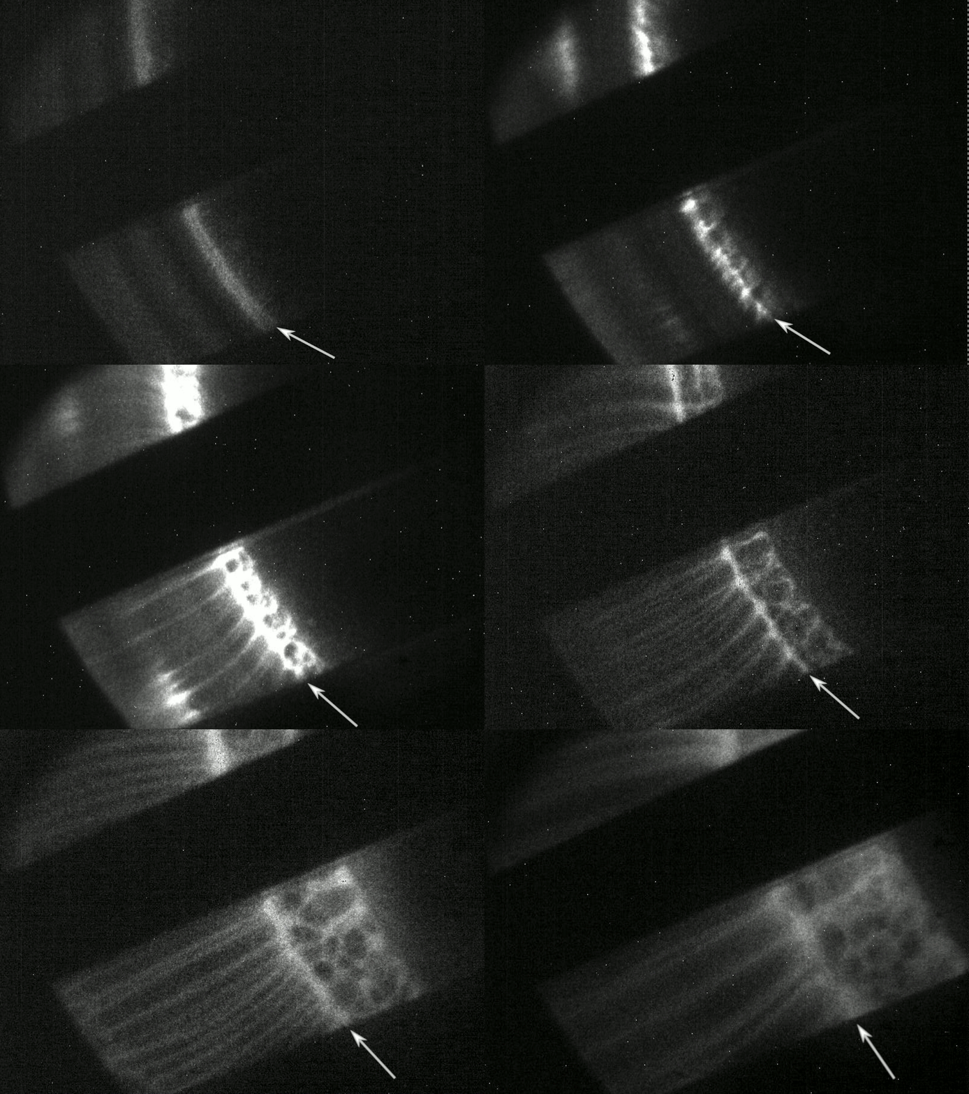
Fig. 1 ICCD animation—the sequel. This sequence of ICCD images, taken from November 2019 through January 2020 during similar shots of our FF-2B device now extends from 230 to 1100 ns, almost three times as long as our previous series (see Jan. 22 report). The images show what appears to be shock waves (bright wavy line) propagating through the current sheath, disrupting the filaments as it goes. This is a side view, looking at the sheath through the gaps between the cathode vanes (black strips). The insulator is to the left and the end of the anode is off-screen to the right.
But more data make for better hypotheses. In December 2019 and January, 2020, we were able to get additional images from later in the current pulse—extending up to 1100 ns, about two-thirds of the way to the peak of the current. They showed that a double sheath was not a good explanation of the images. Two sheaths would have traveled at almost the same velocity, with the rear one traveling about 90% of the distance that the front one traveled. Instead our new images showed that the line separating the orderly filaments and the disordered ones traveled only a bit more than half as fast as the leading edge of the sheath.
What’s going on here? We think the most likely explanation is a shock wave traveling back along the current sheath, disrupting the filaments as it travels. A shock wave (a wave traveling faster than the speed of sound in the plasma) would be created when the current oscillations that we’ve observed caused the current to rise, fall, then rise again.
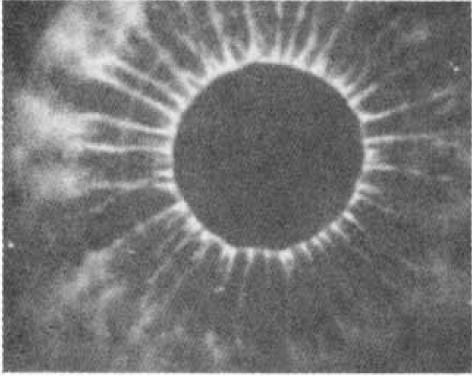
If this hypothesis is correct, eliminating the dip in the current due to the oscillation in the current will also eliminate the shock, allowing the filaments to be orderly and symmetric all the way into the compression phase. From other researchers’ work, we can see that lower-current machines, that have small oscillations also have orderly filaments (Fig. 2).
|
|
Fig. 2, Images of filaments in a smaller plasma focus device, showing orderly filaments and no shock wave. The view is looking along the axis of the anode (central dark circle). (Image from plasma-focus pioneer Winston Bostick).
The good news is this: if we require that the current not drop, the new switches will likely provide that. The switches will allow a faster rise in the current and a greater peak current. By making the rise time about 20% shorter and the peak current about 20% higher, they will make the rate of current rise over 40% higher. Right now, for these last shots, the oscillations were only 5-10 % larger than the current rate of rise. (Figure 3) But if the oscillations get no bigger—and we don’t see why they should—then with the new switches the oscillations will be less that 75% of the size needed to produce a dip in the current—they will only produce a ripple, but no dip. So, we can expect no shockwave.
|
|
Figure 3. In one of the last shots we took on January 17, shot 4, the dip in current (shown here at 55 ns) due to oscillations is barely noticeable. The faster rise time in current that we expect with the new switches should eliminate the dip altogether.
|
|
|
|


No comments:
Post a Comment