
This ends with an excellent summary of current fusion progress for all participants. Otherwise we discuss the resolution of current technical issues at LLPFusion.
It is never easy to get it right but that is the nature of the beast.
We might get spoiled.
Switch Problem Slowdown: Progress Made
The new switches on LPPFusion’s FF-2B experimental fusion device are taking much longer than expected to optimize, but the research team has made progress in identifying problems and solutions for this hold-up. (See our new videos here and here.) The switches are designed to increase current delivered to the plasma, increasing fusion yield, and to be lower-maintenance than the previous design, increasing the number of shots we can take. However, from our first shots in August, we found that the switches were considerably harder to fire than the old ones and much harder to get to fire together.
Of course, part of the problem was that the 16 new switches are harder to synchronize than 8 old ones. The switches must ideally fire (turn on) within 10 ns of each other. This is so that the current starts out as a thin, even sheath. In that case, all parts of the sheath arrive at the pinch, where compression occurs, simultaneously. The result is high density and high fusion yield. If, however, there are differences in firing time, the sheath is thicker and more uneven, resulting in low density at the pinch and low yield.
In November, after 70 shots, the LPPFusion research team had achieved only about a 70% rate of each switch firing on time. This was not good since it meant in each shot 4-5 switches fired late, or not at all.
By this time, a second basic problem was evident. This was large (3,000 amp) pulse of negative current at the start of the discharge. The big capacitors that store energy for FF-2B are charged positively and thus positive current flows from them to the anode at the center of our device. (This means that the electrons, charged negatively, are actually flowing in the opposite direction—from the outer cathode to the anode, as shown in our animations.) A large negative current pulse before the positive pulse began to flow meant that the electrons started out in the wrong direction and had to turn around, making a mess out of the initial current sheath—like a crowd running on the track in the wrong direction right before the start of a race. We had never seen this negative current pulse with the old switches.
Now, we saw that the bigger the negative current pulse, the worse the pinch and the lower the current yield. (See fig. 1.) There could be only one source of the negative pulse - the trigger system that causes the switches to fire. The trigger system sends a 60-kV negative pulse of electricity simultaneously to all 16 switches. This negative voltage, appearing on the central pin of the spark plug, combines with the 40 kV positive on the bottom plate (attached to the capacitor) to create a 100 kV spark that causes the insulating gas to ionize and allows current to flow from the upper to lower plates. (See fig. 2).
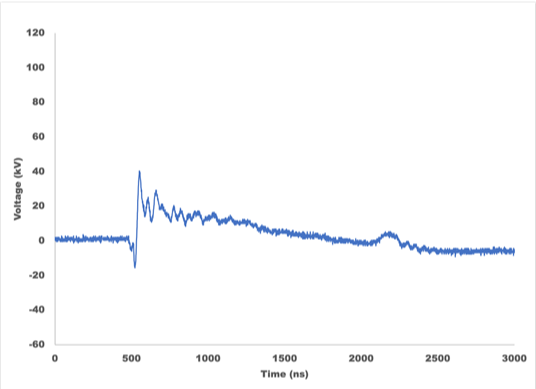
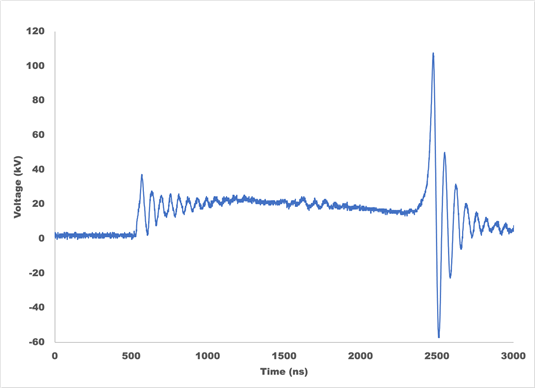

Figure 1. A negative electric pulse of current and voltage is a key symptom of switch misfiring and a key cause of low fusion yield. A typical recent shot (Feb.7, 2022, shot 2, top) shows a starting negative pulse on the left of the graph and a very small jump in voltage at the pinch, indicating a poor compression. A much better shot from 2016 (May 23, 2016, shot 1, middle) shows no initial negative pulse and a large voltage spike (producing 40 times more fusion energy). The graph at bottom shows that the larger the negative pulse, the smaller the best fusion yield for that level. The best shots show only an initial positive pulse.
However, in a misfiring switch, the breakdown can first occur horizontally, running along the insulator from the central pin to the top plate. In this case, a negative pulse appears at the anode, which is connected to the top plate. The vertical spark from the capacitor can also be delayed, because the negative charge is rapidly dissipated on the top plate.
While we did not initially have a clear idea of why this horizontal breakdown was happening, Chief Scientist Eric Lerner first suggested mitigating it by decreasing the gap between the central pin and the bottom electrode. This would make vertical breakdown easier, without changing the horizontal situation. To prevent a premature breakdown, or prefire, we simultaneously increased the gas pressure in the switch. There was only limited improvement in the firing and negative voltage.
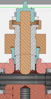
Figure 2. This cross section of a spark plug and the central portion of a switch show the central pin of the spark plug(brown) surrounded by the insulator (light grey) which in turn is mounted on the top plate of the switch (pink). In correct firing, a negative 60kV spark jumps from the central pin across the gas-filled gap (dark grey) to the 40kV positively charged bottom plate (orange). Ionization spreads throughout the gas, allowing positive current to flow directly from the bottom plate to the top plate and from there to the anode of the device (far off the left edge of this image). In misfiring, the spark instead runs horizontally along the surface of the insulator to the top plate, creating a pulse of negative current.
In December, we found a third problem with the switching system. Resistors are part of the triggering system, used to absorb part of the energy of the trigger pulse and to allow the right amount of current through to the switch. We found that many of the resistors had partially failed, losing their ability to conduct electricity at low voltages and interfering with it at high voltages. Higher-power resistors were required to prevent failure. However, such higher-power resistors also slowed down the rise of the trigger pulse. This gave more time for the horizontal breakdown to occur.
The problem with the higher power resistors was that they have higher inductance. Inductance is a measure of how much magnetic field energy is generated for a given current. Since it takes time to feed energy into the magnetic field, higher inductance means a slower rise time for the pulse. The trigger pulse needs to rise to a peak in less than 20 ns if a horizontal breakdown was to be avoided. The solution, we quickly realized, was a different type of resistors, called Aryton-Perry, that had low inductance. We ordered these in early January.
In the meantime, in January a hypothesis emerged about the likely cause for the switch problems and negative current pulse. In designing the new switches back in 2019, we had noticed that the Lexan insulators that surrounded the central pins in the spark plugs, preventing horizontal breakdowns, were degrading after repeated firing (Fig.3, left). We decided that a shift to ceramic insulators would improve the sparkplugs, as ceramics, such the aluminum oxide we chose, are both good insulators with high dielectric constant (a measure of a material’s ability to store electric energy) and are highly resistant to the high temperatures that occur briefly when the switches fire.
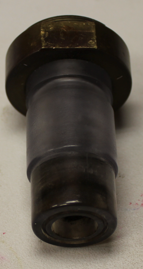
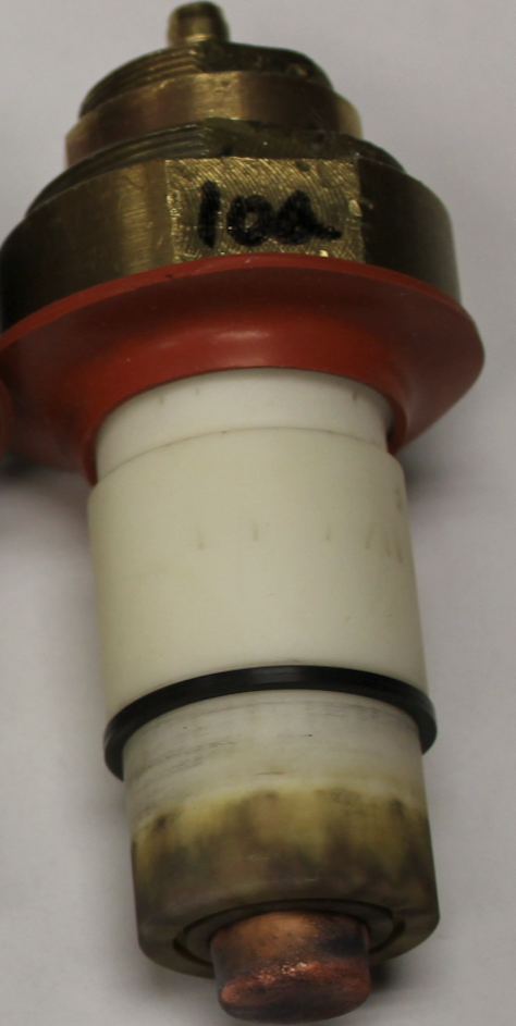
Figure 3. The darkening of the Lexan insulators (left) led the LPPFusion team to replace then with ceramic ones (right). However, the ceramics were much more prone to surface breakdowns within the switch, as evidenced by the dark stripes on the bottom of insulator, near the copper center pin. They also had breakdowns outside the switch, as evidenced by the thin dark marks on top and in the middle of the insulator, which the red rubber guard also failed to stop. We now have a more effective guard at the top of the insulator. Teflon is better at resisting surface breakdown than either Lexan or the aluminum oxide ceramic, so will be tried next.
But now, Lerner concluded that several clues indicated that ceramics were not the right material and instead were the root of the switch problems. First, and most obviously, the purpose of the insulators was to hold off the horizontal breakdown and clearly the ceramics were failing while the Lexan had succeeded. Second, the ceramics’ high dielectric constant meant that more energy was needed to build up the electric potential on the pins, slowing down firing. But most conclusively, in late January Lerner found in the literature research that showed experimentally that ceramics had worse surface breakdown resistance than Lexan, and that Teflon was considerably superior to either.
One such paper dated back to 2007 and was the result of very similar switch problems that had been experienced at the giant Z-machine facility at Sandia National Labs. The authors of this paper found that Teflon resisted surface flashover better, and resisted damage far better, than Lexan. Significantly, the authors concluded that the higher the dielectric constant, the worse the surface breakdown performance. Teflon has a dielectric constant of 2 (measured as a ratio to that of vacuum), Lexan’s constant is 3 and aluminum oxide’s is 10, a strong indication that ceramics are wrong for this application.
The same Texas Tech research team that wrote this paper had already, in 2004, demonstrated that, aluminum oxide flashed over in moist air much easier than did Lexan. The LPPFusion team found evidence of this external flashovers on our own ceramics (Fig. 3, right), although we found a way to block the spark before it reached the ceramic. A much more recent (June 2021) paper by a Chinese team showed the Teflon also damaged less easily than either Nylon or Plexiglass (acrylic). Based on all this evidence, Lerner ordered in early February a set of replacement Teflon insulators.
While waiting for the new insulators, on the suggestion of LPPFusion Research Scientist Dr. Syed Hassan, the team tried lowering the switch pressure and increasing the switch gaps. Using also the new Aryton-Perry resistors, this approach succeeded, in one shot, in getting all 16 switches to fire together. But this success was not repeated, and even in this one shot the negative current pulse got bigger and the fusion yield smaller. These experiments showed that, with low enough gas pressure, the switches could more or less simultaneously break down in both directions, horizontally and vertically. But the negative current pulse so disrupted the formation of the current sheath that almost no fusion yield resulted. Trying somewhat different gases in the switches also failed to stop the negative pulses.
The new Teflon insulators are expected by the end of February. The team will soon run critical tests to see if Teflon will glide us forward to higher fusion yield.
Some fusion fans may ask “If this was in the literature, why didn’t Lerner find it earlier?”, especially considering both papers were published in a journal, IEEE Transactions in Plasma Science, that Lerner has long subscribed to. The answer is that back in 2004-2007, there was as yet no funding for the present stage of the project and engineering considerations were far off. As to why these papers were not searched for in 2021, the fact is that to both Lerner and Hassan, the ceramics seemed the logical choice. As a comedian (not Mark Twain) said, “It’s not the things you don’t know that hurt you most. It’s the things you know for certain that just ain’t so.” Such wrong turns are common in research, which almost never moves in a straight line.
LPPFusion in London Art/Science Show
LPPFusion was among the participants in the Periastra exhibition at the APT Gallery, 6 Creekside, London SE8 4SA. As described on their website “Periastra is a hybrid exhibition where artists and astrophysicists are invited to share each other’s modes of exploring the world of celestial phenomena. Often thought of as mutually exclusive, there are sometimes surprising similarities in terms of the aspiration and expression of curiosity. The participants in this show have been identified through their interest in crossing this boundary and the result is an intriguing and visually rich interpretation of each other’s' fields of research. “
LPPFusion’s part in the exhibition describes how key concepts in our fusion work were derived from research in astrophysics and includes video from our lab projected life-size on the gallery wall, creating the illusion that the lab is an extension of the gallery. The exhibition was free and ran from Feb 3 to Feb 13.

LPPFusion Chief Scientist Lerner (in front of green door) appears to be virtually transported to London in this image from the Periastra exhibit, using video shot at LPPFusion’s lab in Middlesex, NJ.
New Advances by JET and NIF
The world’s two largest government-funded fusion experiments, the Joint European Torus (JET) in Culham, UK and the National Ignition Facility (NIF) in Livermore, Ca., both announced significant advances in the past month. JET stated in a February 9 press release that they had broken their own record for fusion yield. NIF published in the leading scientific journal Nature the achievement of a “burning plasma” and a new record fusion yield as well. What is the significance of these achievements and how do they affect other fusion efforts like LPPFusion’s?
NIF’s advances represented the greater rate of improvement, especially in terms of fusion yield. The $5 billion NIF device, completed in 2009, uses 192 giant lasers to concentrate energy on a tiny pellet of deuterium-tritium fusion fuel. (Deuterium and tritium are isotopes of hydrogen.) While it is the claim that the Nature article most emphasizes, the “burning plasma” milestone is less significant. Burning plasma is, by the NIF’s scientists’ own definition, one in which the power generated by fusion reactions exceeds that supplied by external sources—in this case the lasers. But getting above that threshold does not in fact guarantee by any means that the fusion reaction will sustain itself. That more challenging threshold is when fusion energy generated exceeds the energy lost by the plasma, so it heats up by itself. This condition is termed “ignition”, the central goal of NIF, as indicated by its name.
But the Nature article also refers to the August, 2021 shots that produced 1.3 MJ of fusion energy. This is a big step forward for NIF. By 2013 NIF’s maximum fusion yield was 10kJ, little more than 0.002% of the more than 440 MJ fed into each shot of the machine. In 2018, NIF’s maximum yield rose to 54 kJ. The new results of 170 kJ in the “burning plasma” shots and 1.3 MJ in the August 2021 shot are thus major increases, with the last one producing 25 times as much energy as in 2018. This rapid progress in the course of the 2021 experiments does demonstrate how major advances in fusion can happen quickly, and could help the credibility of other fusion efforts like our own.
However, NIF remains far short of the real goal of all fusion energy research—producing more energy out of a device than is put into it. The latest record is still only 0.3% of the input energy. In addition, NIF is physically incapable of achieving net energy production. Even if all the fuel in the pellet underwent fusion reactions, which is almost impossible, the total energy released would still be only 15% of the energy fed into the gigantic machine in a single shot.
JET’s new results actually managed to somewhat exceed NIF’s in terms of the critical ratio of fusion energy out to energy input to the device. JET is a tokamak, a $3 billion machine that uses magnetic fields produced by external magnets to confine the plasma where the fusion reactions take place. The new result produced a fusion yield of 59 MJ from an electrical input to the machine of a giant 10 GJ, so fusion energy was 0.6% of input energy, double the NIF result. While NIF certainly could point to rapid progress, the JET result somewhat more than doubled JET’s previous record with the same DT fuel that had been achieved 25 years ago in 1997.
How do these new results compare with those at LPPFusion? The fusion yields and even ratios to input energy can’t be directly compared because LPPFusion is using pure deuterium fuel (DD), not the much-more-reactive deuterium-tritium (DT). Since tritium is radioactive, expensive and time-consuming, additional efforts would be needed just to get a license to use it. Also, DT’s use would make LPPFusion's entire small facility radioactive. As a result of this radioactivity, both NIF and JET must be maintained mainly via remote-controlled robots.
If JETs best results using DD fuel are compared to LPPFusion’s best result using the same fuel, JET is only a little in the lead, with a ratio of 0.6 J of fusion energy for every 100kJ of input. LPPFusion best results are 0.4 J of fusion energy for 100kJ of input. Our goal is to surpass our old 2016 record and JET’s DD results in the present series of experiments. In order to match or exceed the DT fusion yield ratios, we will have to move to using pB11 fuel, which is also far more reactive than pure deuterium.
In terms of ion temperature, LPPFusion already holds the world record, with demonstrated confined ion energy of over 200 Kev (equivalent to over 2 billion K), far higher than the 10 keV reached by JET and the 5 keV reached by NIF. However, NIF achieved enormously higher densities than any other fusion device, while the record for confinement time is actually held by another tokamak, EAST, in China. The combination of density, temperature and confinement time needed to achieve net energy has not yet been achieved by any experiment.
No comments:
Post a Comment